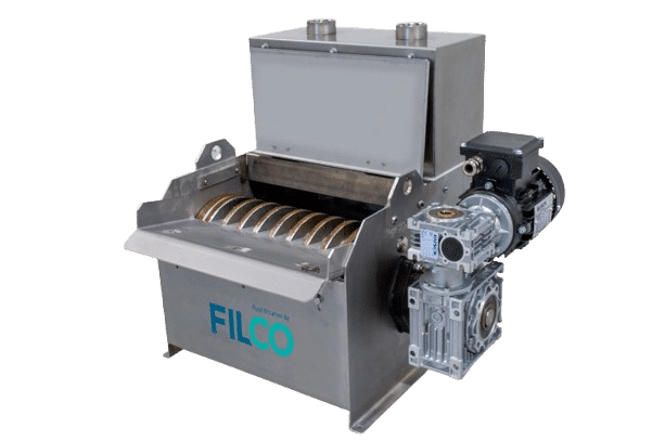
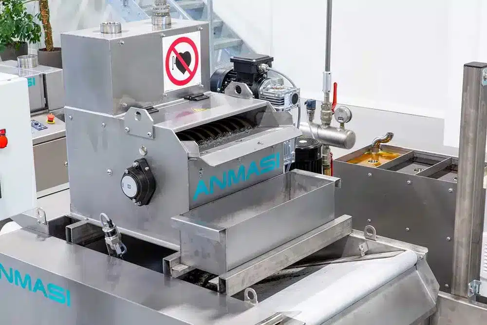
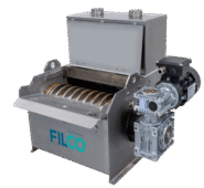
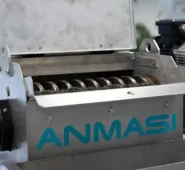
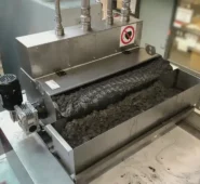
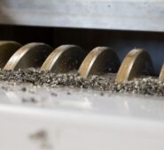
Magnetic Separator
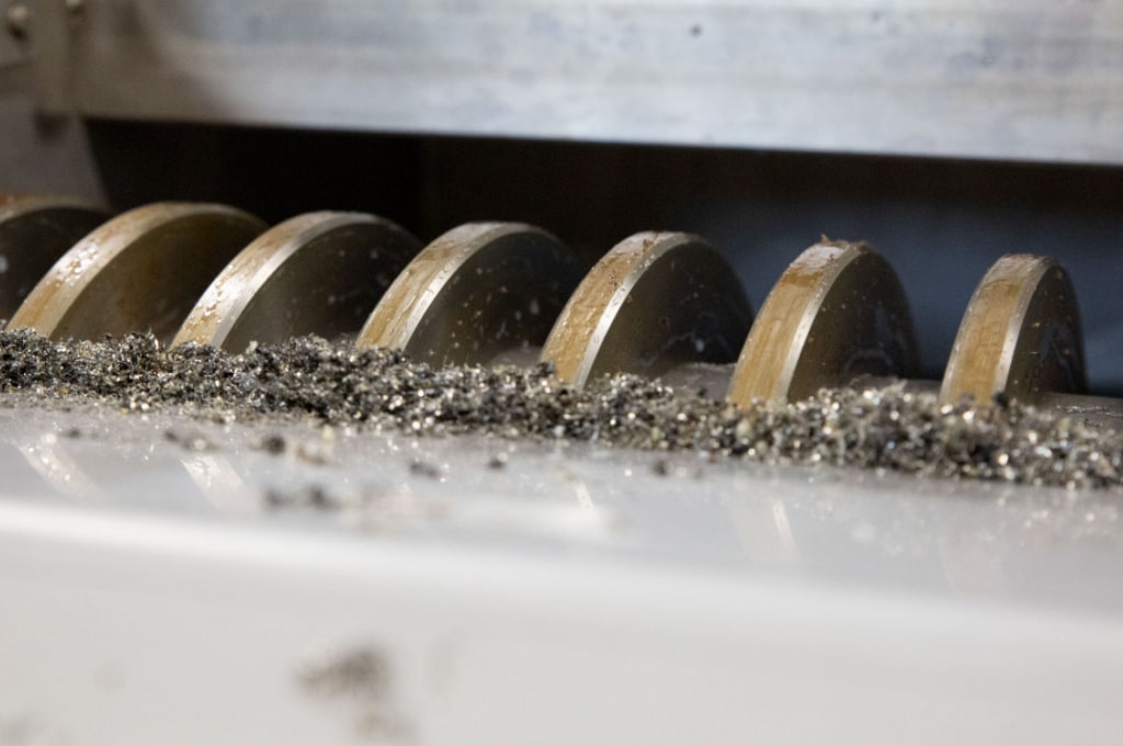
The magnetic separator is extremely effective at removing magnetic particles.
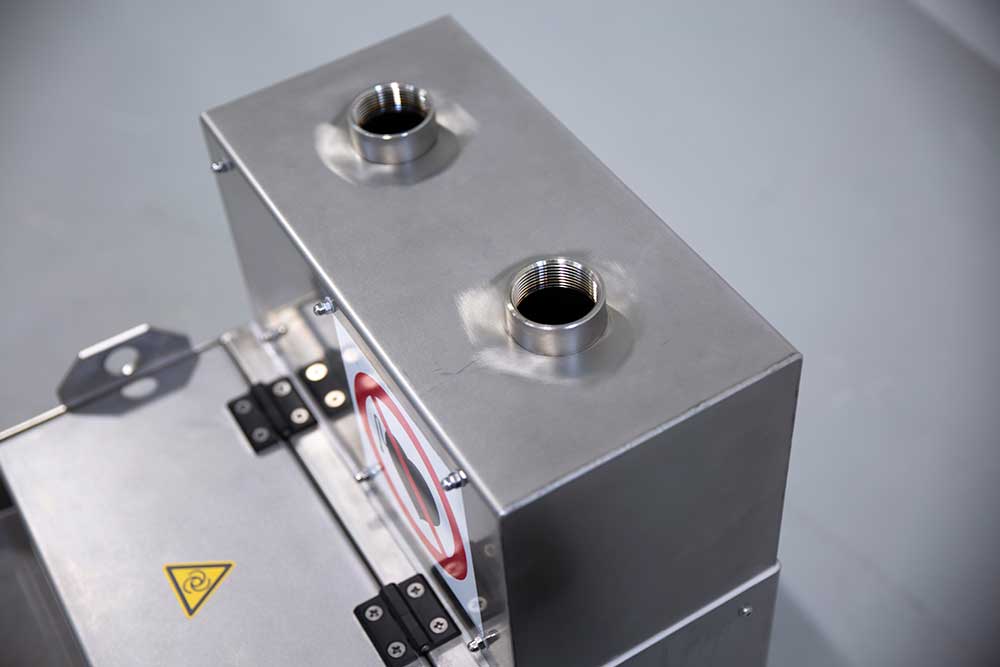
Fluid Manifold
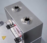
Magnetic separator with a manifold for even distribution of the liquid.
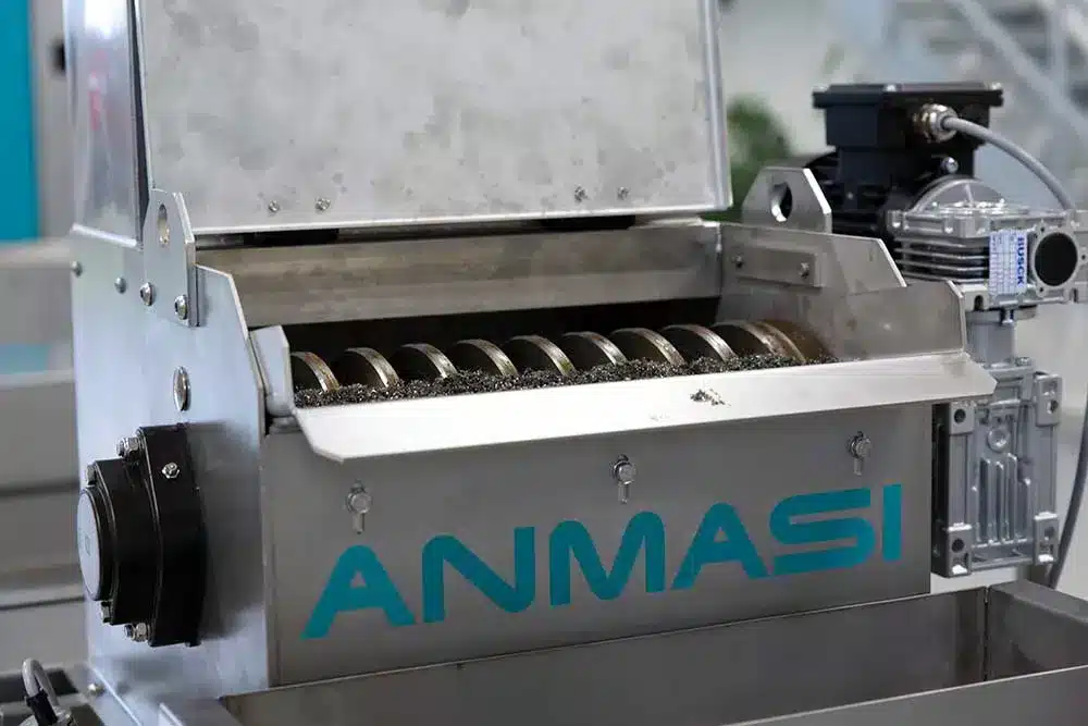
Large magnetic surface
This design improves filtration performance.
Stainless steel
It comes in stainless steel, but it can easily be adapted to work with acid as well.
The EU Machinery Directive
The magnetic separator is manufactured in Denmark in accordance with the EU Machinery Directive.
Effective Removal of Magnetic Particles
from Process Fluids
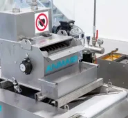
The magnetic separator is easy to integrate into existing systems and is typically mounted directly on belt filters or similar equipment Filtration systems. It comes complete with a manifold for liquid distribution and a sludge box, so it is ready for installation.
Applications
The magnetic separator is used in a wide range of industrial processes where magnetic particles need to be removed from liquids:
- Refrigerant lubricants
- Process fluids
- Oil
- Water Treatment
- Wastewater
Technical Specifications
- Powerful Magnetic Filtration
The magnetic separator is equipped with a very powerful magnet that effectively captures magnetic particles from the liquid flow. The large magnetic surface area ensures high filtration capacity and optimal utilization of the separator.
-
Stainless steel construction
The magnetic separator is supplied in stainless steel as standard. Its design ensures a long service life, high operational reliability, and excellent resistance to demanding industrial environments.
-
Easy installation
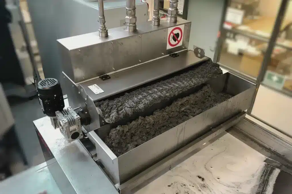
The magnetic separator comes with an integrated manifold for even distribution of the liquid and a sludge box for collecting the separated particles. This ensures optimal operation and simplifies installation.
-
CE-compliant
The magnetic separator is manufactured in accordance with the European Machinery Directive and meets applicable safety and quality requirements.
- Powerful Magnetic Filtration
Modules and Additional Options
- Manifold for fluid distribution
The included manifold distributes the liquid evenly across the separator's surface. This ensures optimal utilization of the magnetic field and the best possible filtration results.
-
Silt Trap
The sludge box collects the separated magnetic particles, making maintenance and emptying simple and efficient.
-
Design for use with acids and corrosive liquids
The magnetic separator is available in a special version designed for handling acidic and corrosive liquids, which place additional demands on material selection and corrosion resistance.
- Manifold for fluid distribution
Table
| Model | Coolant | Oil | Width | Height | Weight | Power Supply | 1 1/2" inlet |
|---|---|---|---|---|---|---|---|
| MS-100 | 100 L/min | 80 L/min | 529 mm | 548 mm | 60 kg | 3x400 V + PE - 50 Hz | 1 piece |
| MS-200 | 200 L/min | 160 l/min | 529 mm | 548 mm | 76 kg | 3x400 V + PE - 50 Hz | 1 piece |
| MS-300 | 300 L/min | 240 L/min | 529 mm | 548 mm | 91 kg | 3x400 V + PE - 50 Hz | 2 pieces (190 mm C-C) |
| MS-400 | 400 l/min | 320 L/min | 529 mm | 548 mm | 102 kg | 3x400 V + PE - 50 Hz | 2 pieces (250 mm C-C) |
| MS-500 | 500 l/min | 400 l/min | 529 mm | 548 mm | 117 kg | 3x400 V + PE - 50 Hz | 2 pieces (300 mm C-C) |
| MS-600 | 600 l/min | 480 L/min | 529 mm | 548 mm | 133 kg | 3x400 V + PE - 50 Hz | 2 pieces (350 mm C-C) |
| MS-700 | 700 l/min | 560 L/min | 529 mm | 548 mm | 154 kg | 3x400 V + PE - 50 Hz | 2 pieces (400 mm C-C) |
| MS-800 | 800 L/min | 640 L/min | 529 mm | 548 mm | 170 kg | 3x400 V + PE - 50 Hz | 2 pieces (400 mm C-C) |